100V

In many background music (BGM) and paging applications, multiple loudspeakers are used. Often mounted in the ceiling, these are low-powered units because they are located close to the listeners walking or sitting below and the nature of BGM is that it is low volume. The listening area of a BGM system is divided in ‘zones’, e.g. a corridor, canteen, waiting area, etc. The purpose of the sound system is to create a uniform sound within each zone. ‘Uniform ‘means that if anyone walks through the zone, the sound pressure level (SPL) fluctuation - or ‘spread’ - should be limited so that it’s not clearly noticed by the listener.
To help design BGM ceiling speaker systems, many loudspeaker manufacturers provide software that automatically calculate the number of loudspeakers needed for a given rectangular area, height, SPL and spread. Yamaha’s software is the Commercial Installation Solutions Speaker Calculator, or CISSCA.
There can be many loudspeakers in each zone - especially in large spaces with low ceilings - each of which can be driven by a separate loudspeaker channel. This means that, if there are 20 loudspeakers, 20 (mono) power amplifiers have to be used. Each loudspeaker has to be connected to its amplifier by a two-wire loudspeaker cable, meaning 20 cables for our hypothetical 20 loudspeakers. If there is a large distance between the amplifiers and the loudspeakers, a lot of cabling is required.
However, because BGM and paging systems need to deliver uniform sound within a zone, all speakers can be fed in parallel with the same signal. This means that only one power amplifier is needed. Similarly, because such applications only need sound delivered at low level, the total power requirement for this single amplifier still falls into the ‘regular’ range, meaning an off-the-shelf unit can be used, saving hardware costs. To make further savings, a single loudspeaker cable can be used in each zone, laid from the amplifier to the first speaker, then to the next speaker, them to the next one and so on.
But there’s a catch. The nominal impedance of market-standard loudspeakers is either 4Ω or 8Ω, with market-standard amplifiers being designed to optimally deliver their power to these impedances. If we designed a system with a zone of 20 loudspeakers with a nominal impedance of 8 ohm and 10W power, wired in parallel to a single power amplifier, the resulting power would be 200W - which would be fine for even a small power amplifier.
However, the combined parallel impedance would be 0.4Ω - causing most power amplifiers to activate their short-circuit protection. Even if this protection was to be bypassed, the amplifier would have to sustain an excessively high output current to achieve the required 200W power - thus overheating and eventually burning out the output circuits. Additionally, the speaker cabling would become a significant factor, dissipating a portion of the power as heat and thereby reducing the system’s effective output power and quality.
Over the years, the market developed the ‘100V’ system as a solution to this challenge.
Firstly, small power transformers are added to each loudspeaker to convert their 4Ω or 8Ω impedance to a much higher value. Most transformers have multiple ‘taps’ to provide volume selection for individual speakers in 3dB steps, either as a wiring option or via a switch. The resulting SPL for each speaker can then be adjusted to fall within +/- 1.5dB, an acceptable spread which listeners would be unlikely to notice.
Secondly, the amplifier output is set to operate at a higher impedance, meaning that a higher voltage is required. For the EU a voltage of 100V is the standard, in the US 70V is used. For high power ratings, regular amplifiers can be used - a 1250 watt power amplifier outputs 100V to a combined 8Ω impedance speaker line. For lower power loads, with higher combined speaker line impedances, a lower-power amplifier can be used - either with specially designed output circuits to support high impedance loads, or by employing a transformer beside the power amplifier to convert its 4Ω or 8Ω output impedance to a higher nominal speaker line impedance.
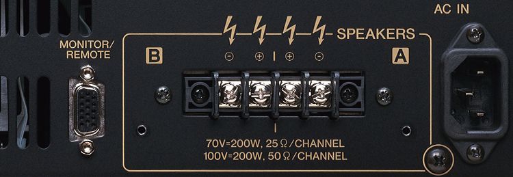
Using 100V speaker distribution to drive BGM zones saves costs. However, because any voltage higher then 50V is susceptible to the EU ‘low voltage directive’ (code 2014/35/EU), 100V systems need additional precautions for connectors and cabling. This is the reason why a 100V power amplifier output terminal has a plastic cover, so users can never touch it by accident. Although the EU directive is called ‘low voltage’, a marking is mandatory to indicate a dangerously high voltage - in many cases lightning icons are used. This isn’t unique to ‘100V’ systems; in the EU it is mandatory for any power amplifier output capable of delivering an output over 50V, or 313 watts to 8Ω, to have the protection cover and markings.


